floorbeams
Back to First Page.|
by John Weaver, P.E. Various field studies have indicated that AASHTO live load distribution factors are too conservative for determining covered bridge floor beam deflections at specific locations. Results at four different sites with various vehicle loads have yielded a variety of results for different types of wood deck and beam combinations, however all results are a fraction of what would be predicted by AASHTO load factors. Of course stiffness of beams relative to deck stiffness and the presence of runner planks above the deck as well as magnitude of live loads and beam spacing all contribute to structural behavior. Measurements indicate maximum deflections ranging from 19% to 58% of those predicted by AASHTO for concentrated live loads. The following table summarizes the results:
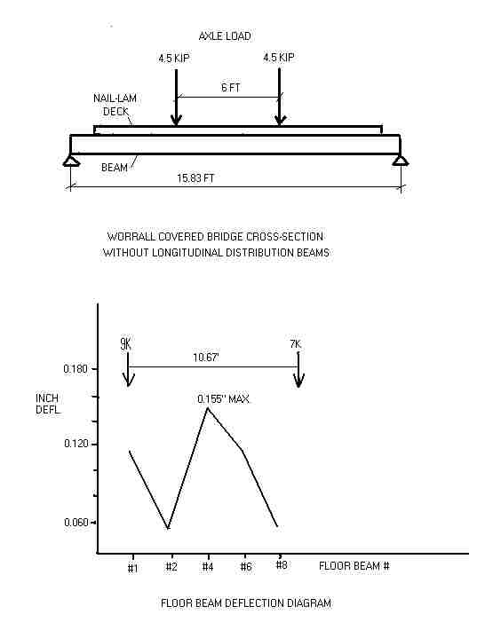
Additionally, Hoyle Tanner Associates, through the University of Maine, demonstrated in a related recent laboratory study that a three beam (6" x 10") nail laminated deck model loaded with a 2.4 kip load placed at the middle of the center beam produced deflection measurements showing that the concentrated load was evenly distributed to the three supporting beams. Unlike covered bridge floor beams, the lab model beams had unyielding supports and the entire system was limited to three transverse beams (@ 3'-6" spacing) with a nail laminated deck system, however the results were interesting and relative to the results of field floor beam investigations. Although the above referenced studies are too limited in scope to establish new general guidelines for floor beam load distribution factors, they do indicate that a specific site and load condition study is required to determine a more exact load factor at (almost) any covered bridge site. A more exact floor beam load factor would yield a more realistic live load capacity analysis of existing beams and reduce size (and resultant dead load) of any replacement floor beams. Attached are the records of member properties, loads and deflection results for the Brown, Worrall and Larkin bridges listed above. Vermont Agency of Transportation has given permission for publication of this data. Cross Sections and site data are copied from 1995 McFarland- Johnson (Phil Pierce) evaluation reports. Floor beam deflection data was derived from field measurements and studies produced by McFarland-Johnson (Phil Pierce) 1993-1994. Note that longitudinal distribution beams at the Worrall and Larkin bridges were loosened before measurements (indicated here) were taken. However these same studies demonstrated that the presence of the longitudinal beams, when connected, had no influence on the maximum magnitude of the floor beam deflections measured. Comstock site data was obtained by the author and assistant in April of 2002. Comstock readings were taken with longitudinal distribution beams attached to the transverse floor beams. Measurements were referenced from either a ledge surface beneath the bridge or tie cross-beams above the bridge deck. Type of Bridge: Plank lattice trusses with sawn floor beams. Floor Beam = 6 x 13 3/4, assume MOE = 1,200,000 psi I = 1/12 x 6 x 13.75 x 13.75 x 13.75 = 1300 in.4, S = 189 in.3 Deflection: AASHTO transverse beam factor = 2.0/5.0 = 0.40 max. live load deflection = (Pa/24EI) (3 x L x L - 4 x a x a)(@ center of beam span) L = 15.83' x 12 = 190", a = (190 -72)/2 = 59" max. live load defl. = (4.50 kip x 59)( 3 x 190 x 190 - 4 x 59 x 59)/(24 x 1,200,000 x 1300) max. live load deflection = 0.669" for entire axle load 40% of axle load yields 0.268" live load deflection @ center of span = AASHTO predicted. greatest floor beam deflection measured @ center of span = 0.155" 0.155"/0.268" = 58% of AASHTO predicted deflection. Estimated Stresses: AASHTO predicted = Pa/S = 4.50kip x 0.40 x 59/189 = 562 psi By deflection measured = 0.58 x 562 = 326 psi
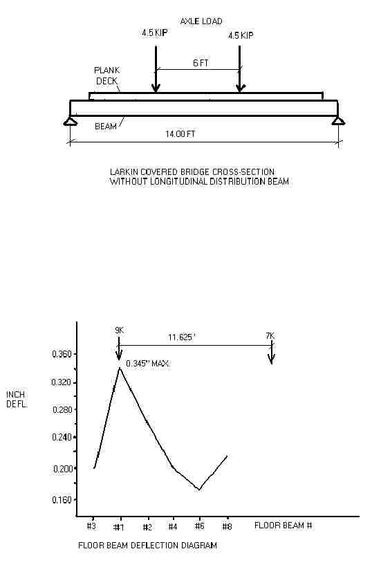
Type of Bridge: Kingpost trusses with sawn floor beams. Floor Beam = 4 x 10 1/4, assume MOE = 1,200,000 psi I = 1/12 x 4 x 10.25 x 10.25 x 10.25 = 359 in.4, S = 70 in.3 Deflection: AASHTO transverse beam factor = 1.75/4.0 = 0.438 max. live load deflection = (Pa/24EI) (3 x L x L - 4 x a x a)(@ center of beam span) L = 14.00' x 12 = 168", a = (168 -72)/2 = 48" max. live load defl. = (4.50 kip x 48)( 3 x 168 x 168 - 4 x 48 x 48)/(24 x 1,200,000 x 359) max. live load deflection = 1.576" for entire axle load 43.8% of axle load yields 0.691" live load deflection @ center of span = AASHTO predicted greatest floor beam deflection measured @ center of span = 0.345" 0.345"/0.691" = 50% of AASHTO predicted deflection. Estimated Stresses: AASHTO predicted = Pa/S = 4.50kip x 0.438 x 48/70 = 1352 psi By deflection measured = 0.50 x 1352 = 676 psi
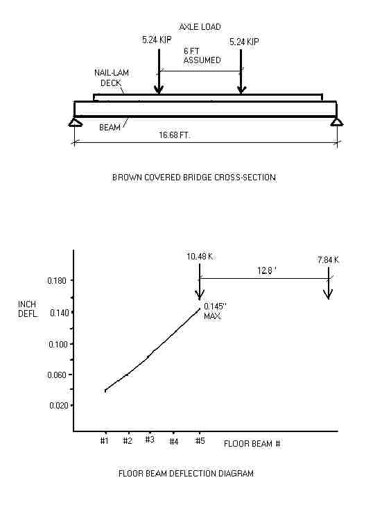
Type of Bridge: Plank lattice trusses with sawn floor beams. Floor Beam = 5 1/ 4 x 11 1/4, assume MOE = 1,200,000 psi I = 1/12 x 5.254 x 11.25 x 11.25 x 11.25 = 623 in.4, S = 111 in.3 Deflection: AASHTO transverse beam factor = 2.0/5.0 = 0.40 max. live load deflection = (Pa/24EI) (3 x L x L - 4 x a x a)(@ center of beam span) L = 16.68' x 12 = 200", a = (200 -72)/2 = 64" max. live load defl. = (5.24 kip x 64)( 3 x 200 x 200 - 4 x 64 x 64)/(24 x 1,200,000 x 623) max. live load deflection = 1.94" for entire axle load 40% of axle load yields 0.775" live load deflection @ center of span = AASHTO predicted. greatest floor beam deflection measured @ center of span = 0.145" 0.145"/0.775" = 19% of AASHTO predicted deflection. Estimated Stresses: AASHTO predicted = Pa/S = 5.24kip x 0.40 x 64/111 = 1209 psi By deflection measured = 0.19 x 1209 = 230 psi
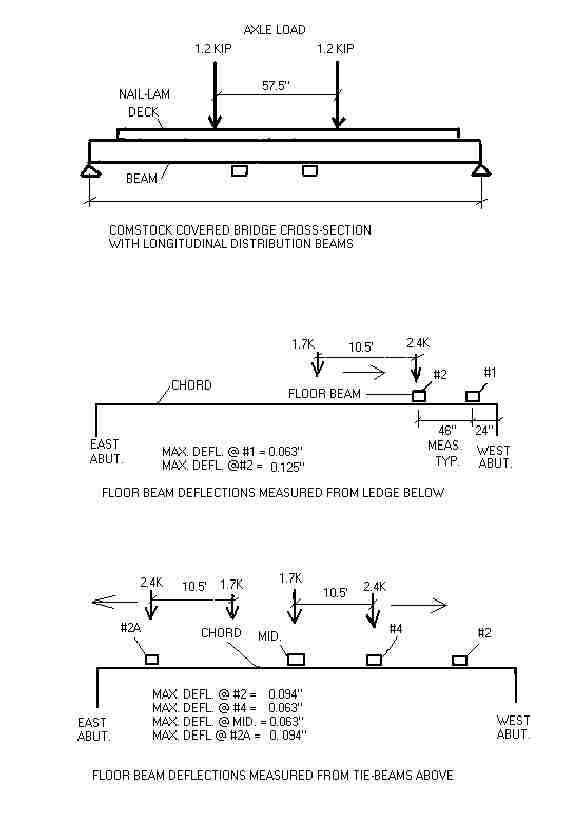
Type of Bridge: Plank lattice trusses with sawn floor beams. Floor Beam = 7 3/4 x 11 1/2, assume MOE = 1,200,000 psi I = 1/12 x 7.75 x 11.5 x 11.5 x 11.5 = 982 in.4, S = 171 in.3 Deflection: AASHTO transverse beam factor = 4.0/5.0 = 0.80 max. live load deflection = (Pa/24EI) (3 x L x L - 4 x a x a) (@ center of beam span) L = 17.83' x 12 = 214", a = (214 -57.5)/2 = 78" max. live load defl. = (1.20 kip x 78)( 3 x 214 x 214 - 4 x 78 x 78)/(24 x 1,200,000 x 982) max. live load deflection = 0.374" for entire axle load 80% of axle load yields 0.299" live load deflection @ center of span = AASHTO predicted greatest floor beam deflection measured @ center of span = 1/8" = 0.125" 0.125"/0.299" = 42% of AASHTO predicted deflection. Estimated Stresses: AASHTO predicted = Pa/S = 1.2 kip x 0.80 x 78/171 = 438 psi By deflection measured = 0.42 x 438 = 184 psi
|
 Joe Nelson, P.O Box 267, Jericho, VT 05465-0267
Copyright © 2003, John Weaver
This file posted October 18, 2003